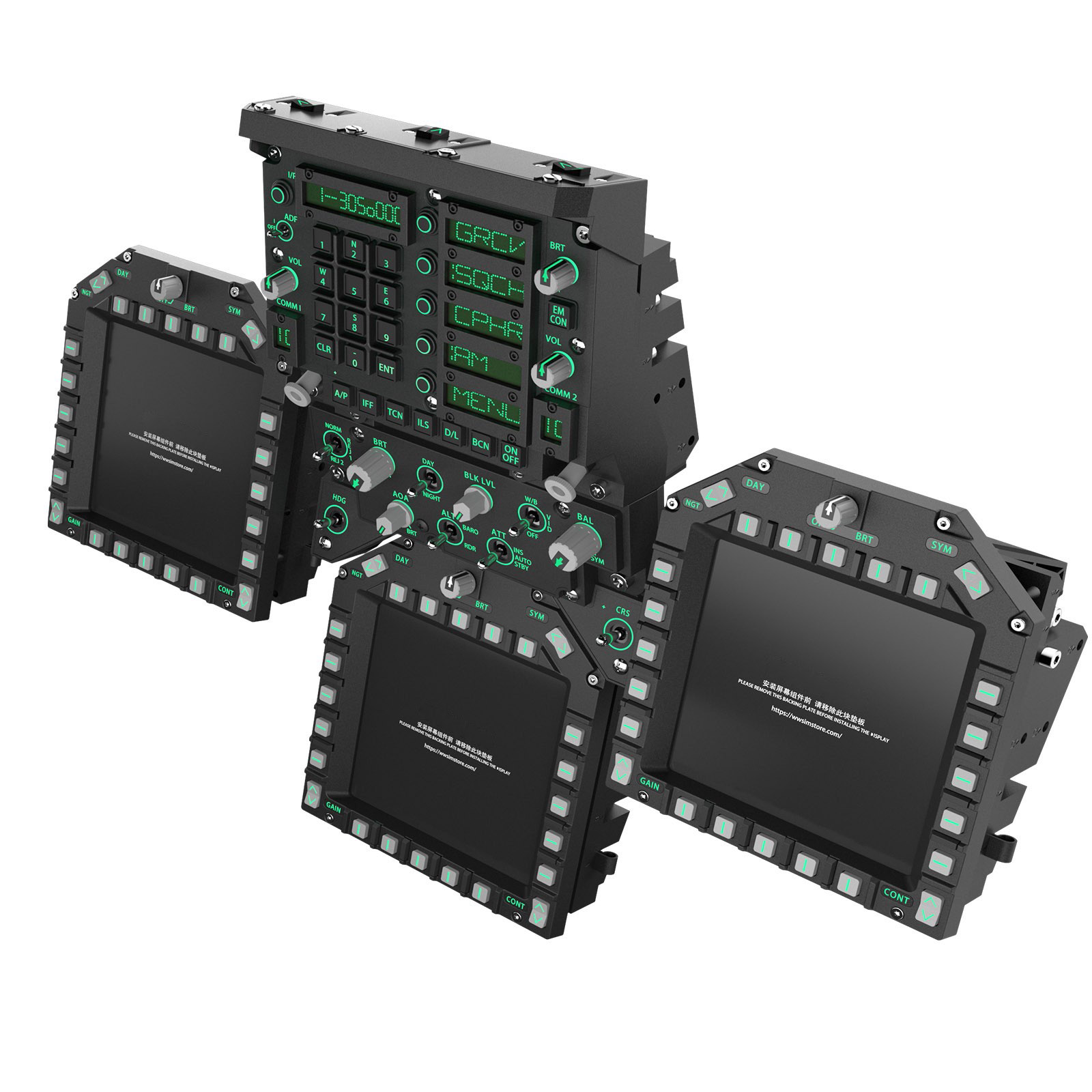
The WINWING F/A-18C MIP gives you the genuine bezel buttons around each display, but the display glass itself is empty. PassthroughForge closes that gap: DCS can export each cockpit display to a rectangle on your desktop, and PSF's Capture Monitor Region grabs that rectangle and shows it in VR as a mask. Park that mask exactly in the panel opening, world-lock it, and the dead glass comes alive — while everything around it (your real hands and the real buttons) stays visible through normal passthrough.
- PassthroughForge set up and working in VR (do the Getting Started guide first if you haven't).
- Your WINWING MIP physically mounted where it belongs in your pit.
- A text editor for one small DCS config file (Notepad is fine).
- DCS — F/A-18C. The same method works for other modules; only the export names change (see the note in Step 1).
How it works
Three links in a chain. DCS paints each display into a fixed rectangle on your monitor; PSF captures that rectangle live; the capture rides on a world-locked mask that you place into the physical panel opening.
The capture pipeline: export → capture → place. Nothing is drawn by hand — it's the live sim picture.
Watch it in action: capturing a DDI screen region and pinning it into the real panel.
Export the 3 DDIs in DCS
DCS decides where each display is drawn using a monitor config — a tiny Lua file. You give each display a named rectangle; DCS renders it there every frame, even in VR. Create the file here:
C:\Users\<you>\Saved Games\DCS\Config\MonitorSetup\DDI Export.lua
(Use DCS.openbeta instead of DCS if that's
your install. If the MonitorSetup folder doesn't exist, create it.)
Paste this and save:
_  = function(p) return p; end;
name = _('DDI Export');
Description = 'Main camera + F/A-18C MFCDs exported to right of primary'

Viewports =
{
     Center =
     {
          x      = 0;
          y      = 0;
          width  = 3840;
          height = 2160;
          viewDx = 0;
          viewDy = 0;
          aspect = 3840 / 2160;
     }
}

UIMainView       = Viewports.Center
GU_MAIN_VIEWPORT = Viewports.Center

-- Three 1280x1280 squares in a row along the top of a 3840x2160 desktop.
LEFT_MFCD   = { x = 0;        y = 0; width = 1280; height = 1280 }   -- left  DDI
RIGHT_MFCD  = { x = 0 + 1280; y = 0; width = 1280; height = 1280 }   -- right DDI
CENTER_MFCD = { x = 0 + 2560; y = 0; width = 1280; height = 1280 }   -- AMPCD


VR_MIRROR = {
 x = 0,
 y = 0,
 width = 3840,
 height = 2160,
 }

-- The key VR line: lets the MFCD exports render even though you're in the HMD.
VR_allow_MFD_out_of_HMD = true
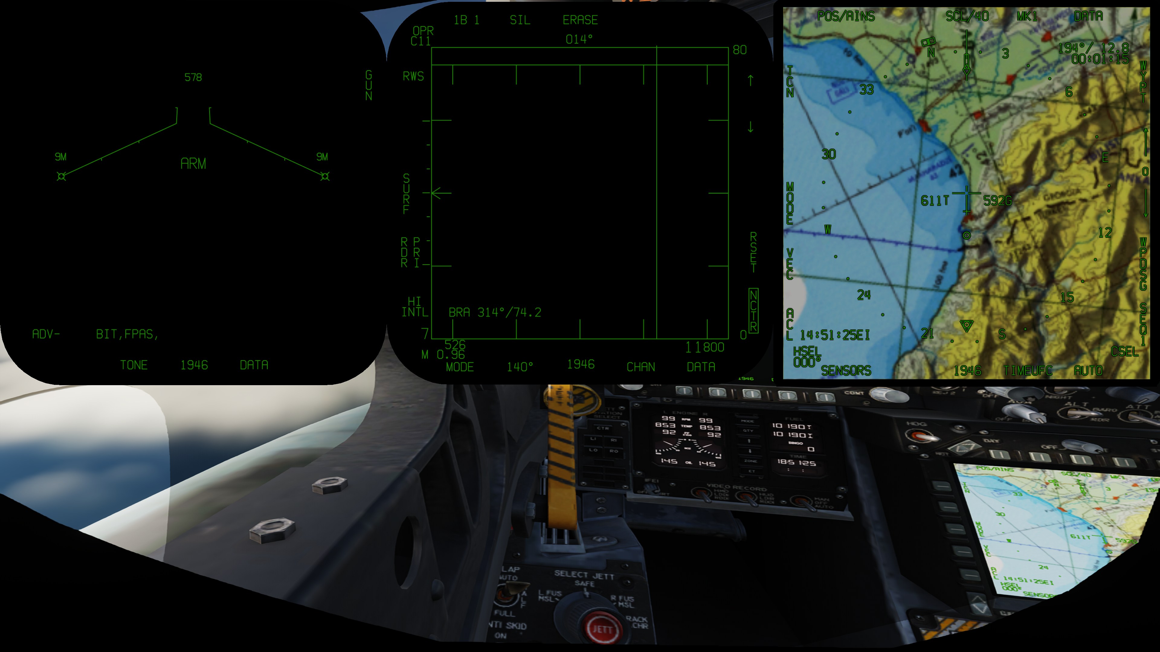
What the config produces on your desktop: three fixed squares PSF will capture from.
VR_allow_MFD_out_of_HMD = true is what lets the exported MFCDs render
to the desktop while you're in the headset — without it, VR swallows the exports
and the squares stay empty. Keep it in.
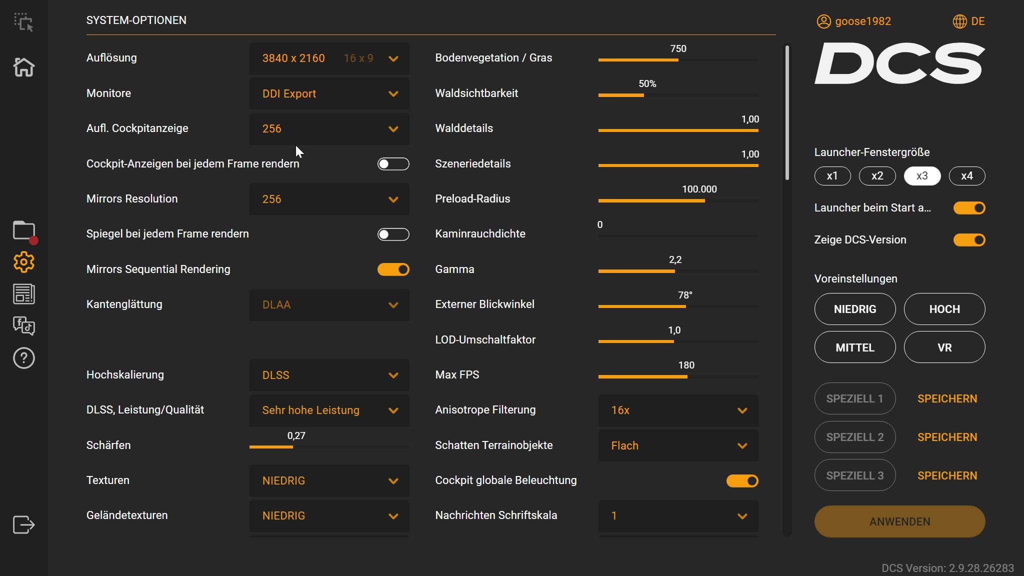
Now tell DCS to use it: Settings → System, set Monitors to DDI Export (the file name), and set Resolution to exactly your monitor's resolution as reported by Windows (Settings → System → Display) — here 3840×2160. Apply and restart the mission.
0,0 → 3840,2160 space. With two or more monitors,
Windows lays them out side by side into one big virtual desktop, and every number has to refer
to that combined space:
- DCS Resolution — enter the total horizontal width (all monitors added together) and the largest vertical height of any single monitor. Not one screen's resolution.
- Lua x / y — position each square in that combined space. To put
them on a monitor to the right, add the primary monitor's width to
x. - Region crop in PSF — careful, this is the one place that's
different: PSF works in per-monitor local coordinates. You pick
the monitor the DDIs are on, and the crop starts from that monitor's own
top-left
0,0. So subtract that monitor's desktop offset from the luax— a square at luax = 2560on the second monitor is cropped atx = 0in PSF.
Dual-monitor example. Say your primary is 2560×1440
(the game view) and you add a 4K monitor to its right for the DDIs. The second monitor
then starts at x = 2560 in the combined desktop, so every square shifts
right by 2560:
Dual monitor: DCS Resolution = 2560 + 3840 = 6400 wide × largest height 2160; the DDIs start at x = 2560.
-- DUAL MONITOR: primary 2560x1440 (game) + 4K monitor to its RIGHT (DDIs).
-- DCS Resolution field:  2560 + 3840 = 6400   x   max(1440, 2160) = 2160
Center      = { x = 0;          y = 0; width = 2560; height = 1440 }   -- primary

LEFT_MFCD   = { x = 2560 + 0;    y = 0; width = 1280; height = 1280 }   -- x = 2560
RIGHT_MFCD  = { x = 2560 + 1280; y = 0; width = 1280; height = 1280 }   -- x = 3840
CENTER_MFCD = { x = 2560 + 2560; y = 0; width = 1280; height = 1280 }   -- x = 5120
In PSF, pick the second monitor — its crops are local, so LDDI x0, RDDI x1280, AMPCD x2560 (= the lua x minus the 2560 offset).
LEFT_MFCD and RIGHT_MFCD are the standard DDI
names; CENTER_MFCD is the Hornet's AMPCD. Other aircraft use their own
export names (e.g. the A-10C's MFCDs, or a Viper's MFDs). If one square stays blank, the name
is wrong for your module — check that module's export documentation and rename the block.
Check the displays actually render
Jump into a Hornet on the ground with power on. On your desktop monitor (headset off, or glance under it) you should see the three squares filled with the live DDI and AMPCD pictures. This is the picture PSF will capture, so get it looking right here first.
Capture each DDI in PassthroughForge
In the PSF desktop editor, make one mask per display:
- Press + Add Mask to open the wizard and choose
“Capture monitor region…”
(Cropped live mirror of a whole monitor).
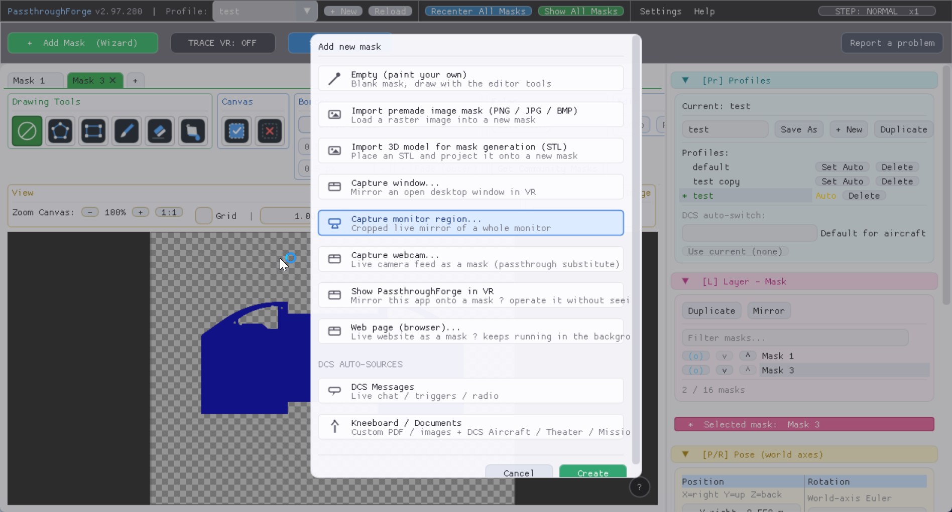
Add Mask wizard → “Capture monitor region…” (Cropped live mirror of a whole monitor). - In the Pick a Monitor Region picker, select the monitor the DDIs render on, then
drag a rectangle around the left DDI square. For a pixel-perfect grab, type the
exact rectangle from your config (
x 0, y 0, 1280 × 1280).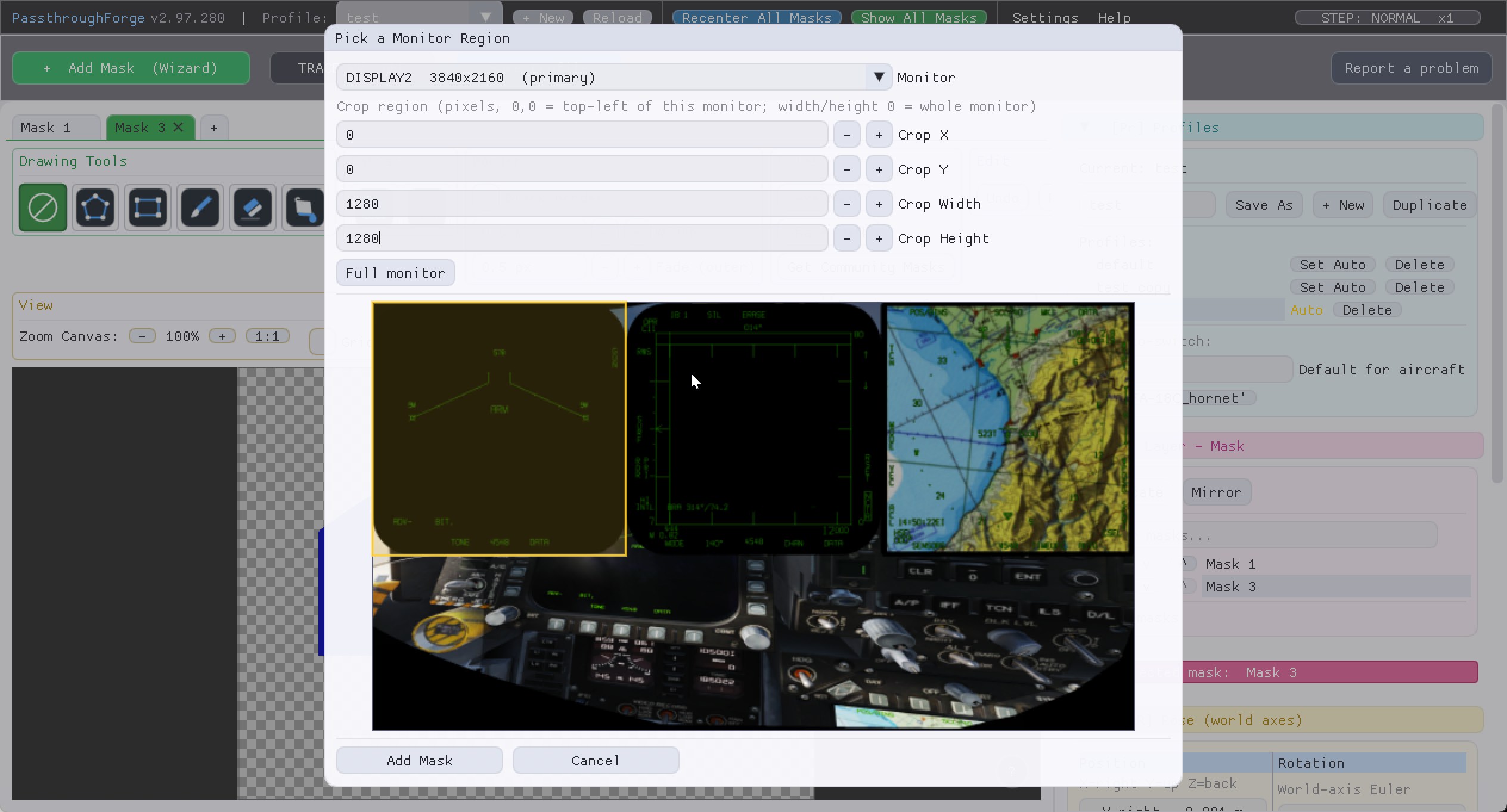
“Pick a Monitor Region”: pick the monitor, then type the crop ( 0 / 0 / 1280 / 1280) — the left DDI lights up in the preview. - Confirm — the mask now shows the live left DDI. Rename it LDDI so the tabs
stay clear.
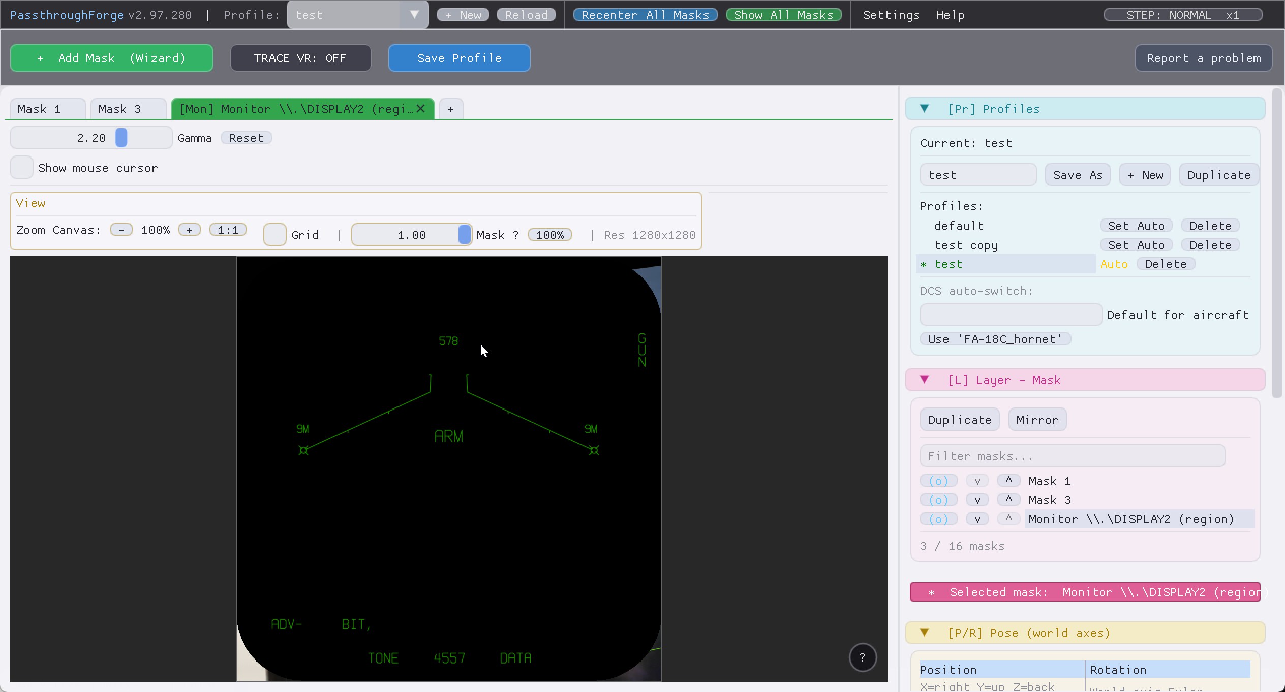
The mask now carries the live left DDI — captured straight from the monitor region. - Repeat for the right DDI (
x 1280, y 0) and the AMPCD (x 2560, y 0) — each1280 × 1280. Three masks total: LDDI, RDDI, AMPCD.
0,0. On a single-monitor setup those match your lua
one-to-one (above). On multiple monitors they don't: subtract the chosen
monitor's desktop offset from the lua x (second monitor at desktop
x = 2560 → crop x = 0). See the
coordinate note in Step 1.
See the real panel around the screens
The captured screens are opaque — they show the display, not reality. To see your real MIP and buttons, the area around the screens has to be passthrough. If your cockpit passthrough already covers the MIP, you're done. If not, add one ordinary passthrough mask over the whole panel:
- Create a normal mask (a see-through window) and shape it to cover the MIP face.
- The three capture masks then sit on top, filling the display openings, while the passthrough shows the real bezel and your hands.
[V] Visibility & Activation) — it forces the mask to draw
above all others in the compositor, regardless of geometry.
Drop each screen into its panel opening
Now the satisfying part: in VR, move each DDI mask so it sits on top of the passthrough window, right in the physical display opening.
- Leave the capture masks on Tracking = None (World) — your MIP doesn't move relative to your seat, so a world-locked screen stays put.
- Select a DDI mask and move / nudge it over the real opening (on top of your passthrough panel), then scale it until its edges meet the bezel. Do it with your head steady in your normal seated position. New to moving and positioning masks? The Getting Started guide walks through it step by step.
- Line up all three: LDDI upper-left, RDDI upper-right, AMPCD lower centre.
- Save Profile. Next session it's one recenter away from perfect.
Target layout on the MIP: glowing captures in the glass, real buttons all around via passthrough.
The payoff — live DDIs and AMPCD sitting in your real panel.
Troubleshooting
| Symptom | Fix |
|---|---|
| A DDI square never renders (not even black) | Wrong viewport name for your module, or it falls outside the resolution. Check the name and that the rectangle fits inside your set resolution (Step 1). |
| DDI square is black but rendering | The display is off / dimmed in the jet. Power it up and raise the cockpit display brightness (Step 2). |
| Capture shows the wrong area or a black border | Re-pick the region and match the config numbers exactly (Step 3). |
| Screen looks washed out / too dark in VR | Adjust the capture Gamma slider on that mask (2.2 matches the VR pipeline). |
| Screen drifts off the panel | Keep the mask on Tracking = None (World), recenter with head steady, re-save. A strip of light tape over the Quest proximity sensor stops the playspace re-centering when you lift the headset. |
| Can't see the real buttons | The MIP area needs passthrough — add a passthrough mask over the panel (Step 4). |
| Captures don't update / frozen | DCS must be running and rendering (it is, in VR). Make sure the region sits on an active display that stays on. |
Stuck? Jump on our Discord — plenty of hardware-pit builders there who run exactly this setup.